Engine Build
August 9, 2004
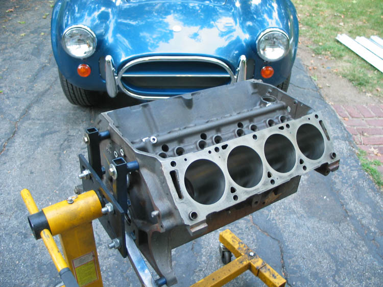
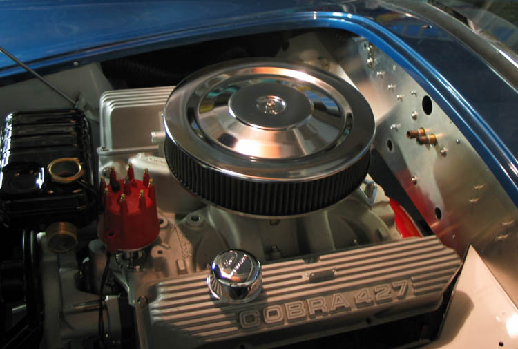
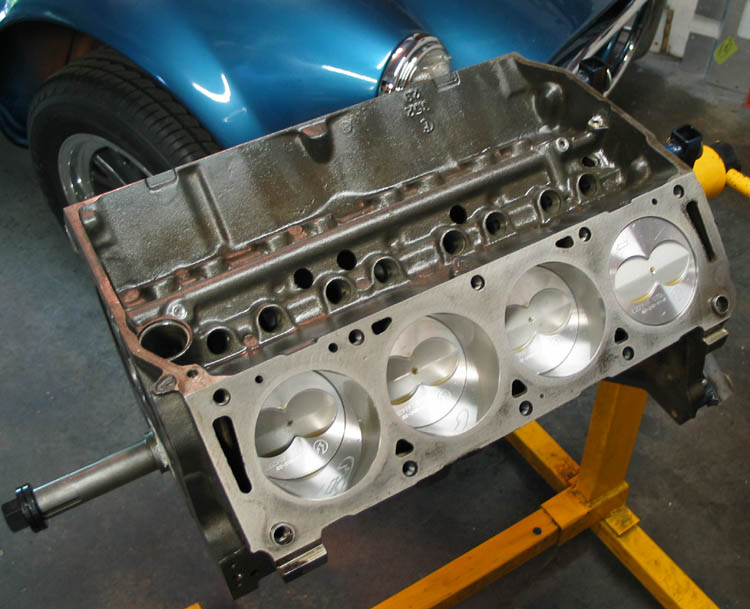
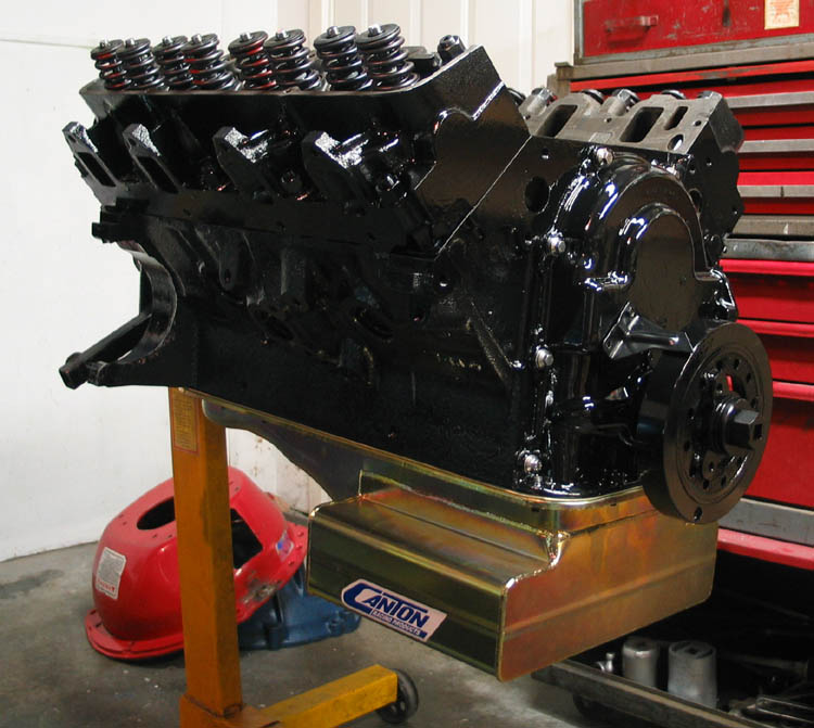
With the bodywork out of the way it is (thankfully) time to get back to building the motor. We are building a standard bore 390 using a 352 block that I took up to Gessford Machine in Hastings, Nebraska to be machined. While I was there we sonic checked the block to be sure it would have plenty of meat for the .050" bore required. It did and then some. They bored it and aligned honed it, and did some oiling mods like matching the main oil feeds to the holes in the bearings. George said I still need to do a final clean on the block so that will be the first project. Then I would like to check clearances on the crank and rod bearings to see if either of them need to be machined. They are supposedly ready to go but I want to be sure. Then the crank, rods, and pistons will go to K&M Machine in Raytown, Missouri to be balanced.
August 11, 2004
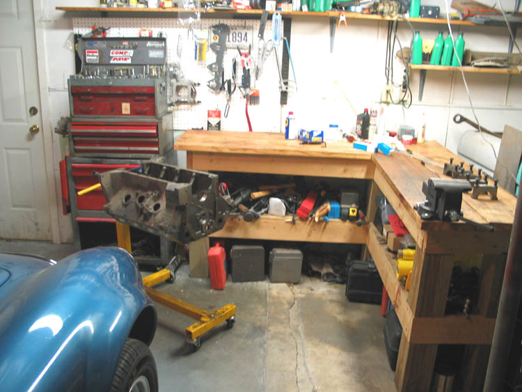
Last night I completed the conversion from paint booth to motor shop and started on the block. Other than the relatively close quarters I think it will be fine with the car in there. I should get a cover for it though. Last night I pulled all the threaded plugs from the engine and ran cleaning taps down all the bolt holes. Tonight I hope to do the final clean on the block.
August 12, 2004
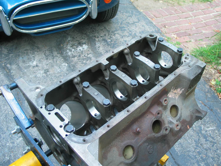
Last night I final cleaned the block using at first a solvent sprayer (made in china) that hooked up to your air hose. It worked briefly and I was able to spray some acetone through the oil galleys. Then using soapy hot water (tide) and a sponge I washed the block everywhere. Using long engine cleaning brushes that I dipped into the soapy water I cleaned out all the oil galleys. There was one that run diagonally up from the oil filter block that I got a lot of crud out of. Then I used the power washer to rinse it well. Then I immediately sprayed it down with WD-40 and started drying it with compressed air. Then another shot of WD-40 and let it air dry the rest of the way (supper time). Next I wiped down the cylinder walls with paper towel soaked with transmission fluid until the paper towel came out clean. Finally I wiped down the cylinder walls, lifter bores, and main bearing saddles with motor oil and bagged it up. Early this morning I cleaned the 427 .020/.020 crank I'm going to use in it and dry fitted it to the bearings to check clearance. Using plastigage (you lay this wax across the bearing surface and torque down the main caps, you then measure how wide it has squished to determine clearance) all journals were consistent and measured .002" clearance. This is within spec but a little loose. The spec from "How To Rebuild Big-Block Ford Engines" is .0005 - .0025 with .0005 - .0015 preferred. However the blueprint spec from 60s Ford racing document "HI-PER PARTS" lists .0025"-.003". So it's a little loose although plastigage only lists 3 decimal places so I could be in the "preferred" spec and not really know it. Since the crank is already ground .020 / .020 I don't want to go further. We'll see how the rod bearings check out next. I think we're okay on the mains, but I'll ask around to be sure.
August 13, 2004
Delays...Delays. I was set to take all the rotating parts to the shop to be balanced today but ended up having to order different main bearings. I was asking around about the clearance and most everyone agreed .002 was just right. But someone mentioned that I really don't want to run full grooved bearings with a full grooved crankshaft like I have. So I asked around about that and George at Gessford said I should run Federal Mogul 125M bearings which are 3/4 grooved. Federal-Mogul Bearing Article And as it turns out they are hard to find in the .020 undersized size. I think I must have found the last set in the country as FM has obsoleted that size. They were expensive with lots of middle men working on their boat payments but I absolutely could not find them anywhere else. They will be here in about a week and at that time I'll have to go back through the clearance issue with the new bearings. I didn't want to spend money on balancing the crank until I knew I had bearings to run it on. In the mean time I've decided to mock up the engine and transmission in the car so I can weld the little connector tabs on the exhaust header pipes. It'll be fun and still feel like progress. Tonight I got motor mounts and transmission mount and a bunch of bolts. Tomorrow I'll get more bolts and give it a try.
August 16, 2004
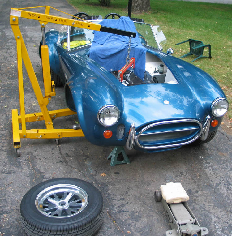
Saturday I got the motor and transmission mocked up in the car and it's really starting to look like something. Too bad there are no guts in the motor yet! My hoist has a fairly short reach so I couldn't go in from the front, I had to go over the side. It worked fairly well though, it's a tight fit but well engineered I thought. Charlie's tip to not put the pan on until you have the motor in the car was important, I'm sure the T shape would give problems. The whole reason to do this is to mock up the exhaust so I can weld little connector tabs between the individual pipes that bolt onto the head and the collector. I haven't welded them yet, I'm going to call out to ERA today for placement tips. I also mocked up the rest of the exhaust to see how it will fit. I'm a little confused about where there should be hangers etc, but it looks like it will work. I kept going and mocked up the top of the motor too, I was real curious to see if the hood would close, with no hood scoop (and resulting hole) it was tight. I had to cut down the carburetor stud and use the shorter hellings & stellings foam air cleaner rather than the slightly taller K&N replacement. I'll have to look for a shorter K&N type element or maybe go to a drop base 14" air cleaner. That foam element is too Briggs & Stratton for me!
August 17, 2004
I may have solved the air cleaner decision this morning. By combining a K&N drop filter base I had with a reproduction 289 K-code top and a 3"x14" filter I have about 3/8" of clearance under the hood. Next I have to make sure the throttle linkage will clear this setup. But it should flow well and I think it will look okay once I get a hipo 427 decal on it.
August 21, 2004
Since the last update a fair amount has happened. I hooked up the throttle linkage and it cleared just fine. So I'm pretty well set on the drop base with K-code top and 3" filter. Next project was welding the connector tabs on the header pipes. The more I looked at the situation the more I really didn't want to weld them on the car. I'm not that confident of a welder, I just don't do it often enough. And because of the short length of the header pipes there are bends near the connection so I would also need to do quite a bit of fitting and grinding of the tabs themselves. So what I did was bolt everything up and get it where I thought I wanted it. Then I drew several lines both around and along the pipes where I wanted the tabs with a sharpie marker. Then I took the pipes off and realigned them on the workbench. This turned out great and I got the tabs welded pretty easily. Then as a final test I bolted everything back onto the car to verify it had worked out, and it did. So the rest of the morning today was spent pulling the motor and trans back out of the car and putting everything back in storage. I will ship the pipes down to oklahoma city to Airborne Coatings to have a silver ceramic coating applied to them. My thinking on this is that these are the special pieces of the undercar exhaust so I want them to last a long time. The muffler and tailpipe could be replaced at midas if I need to so I probably won't do anything to them. On Tuesday we dropped the crank, rods, pistons, etc. off to be balanced. I had hoped they would be done on friday but they weren't. The new bearings aren't in yet either so the motor is at a stand still. Lots of other things to do though, just need to decide what.
August 23, 2004
The balance of the weekend was spent doing a bunch of parts prep for the cobra. I put a bolt through the left engine mount for a torque limit. I also cut about an inch off the bottom of my scattershield for ground clearance as described in the ERA manual using an air powered cutoff wheel. Then on sunday I black powder painted a bunch of small parts like the alternator bracket, down tubes under the dash, clutch slave cylinder bracket, etc. I also bead blasted a timing cover to use on the motor.
August 29, 2004
Well a LOT has happened in the last week on the motor front, I hope I can even remember everything. The first issue was that I got a call on Tuesday from K&M doing the balancing that there was a problem with my "set" of connecting rods. 3 of the rods were over 30 grams heavier than the other 5. They thought this was too much to grind away and that the castings were too different to use. So I ended up buying another set of refurbished rods from Dennis at www.dscmotorsport.com and had him ship them directly to K&M. Also on Tuesday, it turned out that the special 3/4 groove bearings that I thought I had on order really don't exist. So I talked to George Anderson again and he said I could use the bearings I already had, which is good since I really didn't have much choice other than hunting up a different crank. On Friday of this week I picked up the balanced components from K&M, the new rods from Dennis were great and everything checked out good.
In the mean time I started rethinking my camshaft selection. I had a pretty mild hydraulic cam from Crane Cams bought, mostly with putting this motor in my Pickup in mind. Crane Cams H-272-2 I got to thinking that the cobra needed something more. I would really like to see 400HP out of this motor after all the work I put into it, and have it rev to the 6000 rpm rev limiter in the MSD box. So after lots of research and help from guys on the FE motor forum on the internet I decided on an Iskederian Cam. This solid lifter cam should do what I want, has low lift and moderate spring pressures to help my stock valvetrain live longer, it's 108 lobe separation angle will give the car a lopey idle, and it's significant overlap should keep detonation at bay... in theory. Isky EE-360 Cam To implement the switch to solid lifters I will use the heavier valve springs I had saved for the 427 project and have to install smaller valve stem seals, which I had purchased for this motor but wasn't necessarily going to install. I was also able to find this cam and lifters used from another FE motor enthusiast so I even get to try it out for cheap. Here is the predicted benefit of the cam change in Desktop Dyno 2000. One flaw in this simulation is that it uses Edelbrock Medium Riser Head data because I don't have actual flow data for my heads. I expect to loose 50 HP across the board because my heads won't be as good. Still I should see over 400HP!
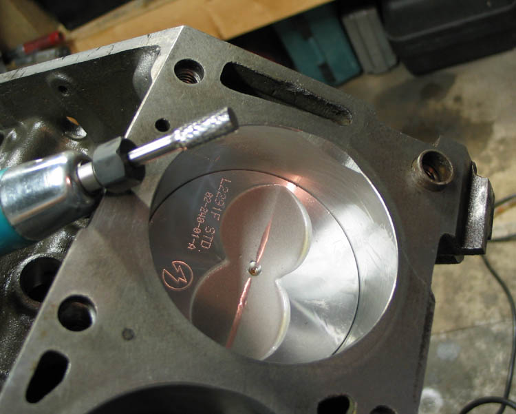
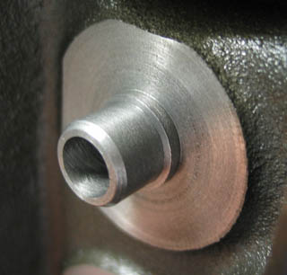
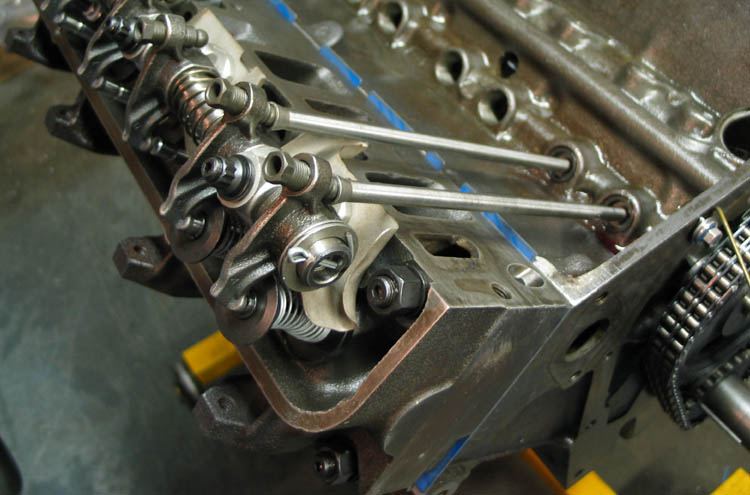
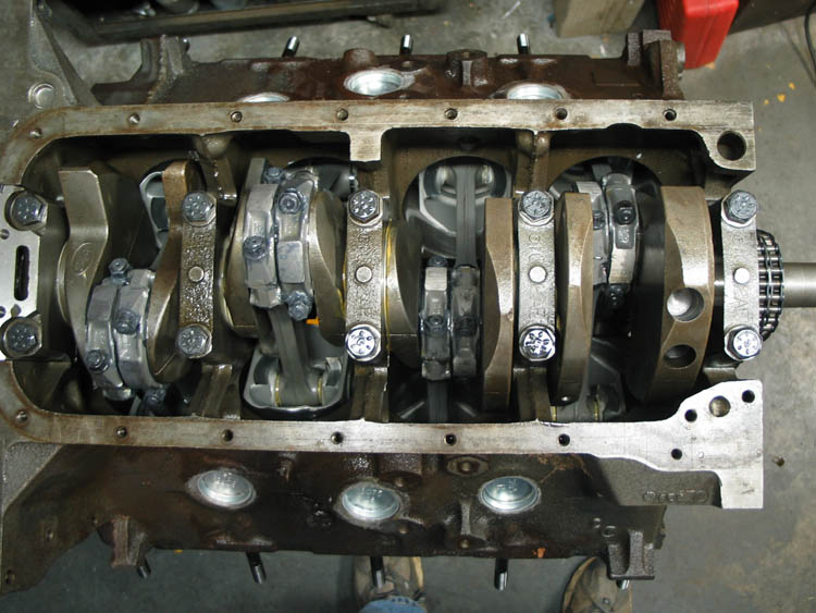
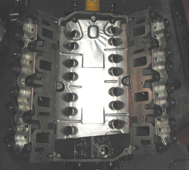
At this point I was anxious to start assembling the short block so Friday night I installed the crank. Everything went together well and crankshaft endplay was right where it should be. Then I started disassembling the heads to do the work to put the new valvestem seals in. Since I had decided on a cam I thought this would be a good time to check the valve to cylinder clearance at the lift of the cam. So I put masking tape on the end of the valves at cam's lift plus a little margin and put the head on the block. There was definitely no contact but it was real close. I knew this could be an issue because of the larger valves I put into the heads. But when I mocked up the engine months ago it looked like it would be okay, but I only tried one cylinder, and there is some variation between cylinders. The rule of thumb is that you should be able to slip a normal sized paperclip between the valve and the cylinder wall and I couldn't. My paperclip measures 0.033". The answer to this is to grind little notches in the very top of the cylinder bore, above where the top ring stops (in the area where the ridge is formed in used engines). This is very acceptable and even the factory did it, the new 427 block I have has these notches in it from the factory to clear the huge valves on the High Riser heads. I did regret that I did not do this machining before the block was final cleaned, but better now than never I figured. To make the notches I bought a cylindrical cutter for my electric die grinder. To keep the chips out of the engine I put a wadded up bath towel in the cylinder bore and covered the rest of the engine with more towels, and masked off the area around the bore I was working on with masking tape. I laid out the max area I should cut to stay away from the ring and get just the closest approach of the exhaust valve (the intake had plenty of room). I did one prototype cylinder and checked the paper clip test again, it passed easily. Then I did all the other cylinders the same way as best I could by hand. I tried to cut the minimum amount and I feel pretty comfortable that I did it right. Most of the chips ended up on me, on the masking tape, and in the bore which were wiped out when I removed the towel. I spent quite a bit of time re-cleaning all the bores and feel pretty good that I got all the chips out.
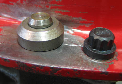
Finally yesterday I installed the first piston. I checked the rod bearing clearance and it was right where I wanted it too at .002". I checked the ring end gap and they were good and so was the ring side clearance. The deck height of the piston turned out to be 0.018" which is about what I was expecting and matches the factory 427 spec. That gives a compression ratio of 9.75:1 with everything considered, which is right where I wanted it with pump gas and iron heads. Below is a picture of the first piston, the notch and the cutter.
September 4th, 2004
Making some progress on the motor today, I had a busy week at work so made almost no progress. I did take the block off the stand for a bit to install the plug that covers the end of the camshaft. Today I finished installing all the rods and pistons. I just snugged the rod bolts because I bought a rod bolt stretch gage which isn't here yet. Supposedly the best way to correctly tighten rod bolts is by measuring how much they stretch. It's a little amazing that when they are tight they have stretched 6 thousandths. Everything went together nicely and all the clearances were good. I covered the shortblock for the time being because the cam has not arrived yet so there isn't much else to do to it until then.
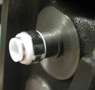
I started working on the heads this afternoon. I needed to cut down the end of the valve guide to accept Crane teflon valve guide seals which are smaller that the ones K&M put on the heads. They need to be smaller to fit inside the dual valve springs required for the solid lifter cam. I had the cutter from Crane and put it in my 1/2" drill. Man did that cut slick! I was done in a few minutes and then used the powerwasher to clean up all the chips and oil. As you can see in the picture the original guide was the size of the ridge at the bottom all the way up, the cutter necked it right down and cut the chamfer at the top. Next I can put the valves back in and install the seals... and then start on the other head.
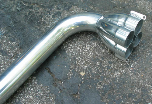
Also I got the headers back from Airborn Coatings in Oklahoma City where they got silver ceramic coated. They turned out beautiful and Airborn got them to me a week sooner and $36 cheaper than they quoted me.
September 8th, 2004
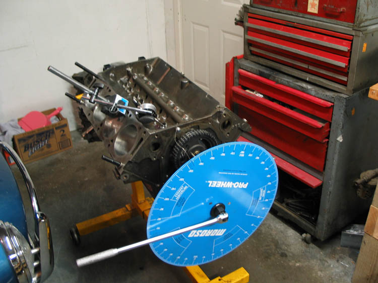
I got the cam last night so I got up early this morning to spend a couple of hours working on the motor. First I put the degree wheel on and found true top dead center. Then I checked all the pistons compression height, they ranged from 0.010 to 0.013, which is less than I originally measured. I then degreed the cam and found that it was ground 2 degrees advanced. I could run it that way, it would give a bit more torque at the expense of some upper end horsepower. It will also help the exhaust valve to piston clearance, I'm a little worried about that. But I think I'll correct it back to straight up with the crank gear. Next I need to mock up the valve train and check piston to valve clearance. I also have no idea if I have the right length pushrods or not... we'll see.
September 10th, 2004
Had another early morning motor fest today. I wanted to recheck the cam timing and I found that I was wrong, it wasn't 2 degrees retarded it was 2 degrees advanced. So I just rewrote history above! I can do that, it's my story, and I'm sticking to it.
I also decided to remove the pistons again (except for #1 for now). I did that for two reasons, first I had a creepy paranoid feeling I should re-check the snap rings on the pins, and also I was having trouble degreeing the cam with all the piston in there, you just can't turn the crank smoothly. I also need to check the centering of the bell housing and I'm sure having just the crank to turn will make that process easier too.
Then I mocked up the valve train to check the pushrod length and the piston to valve clearances. I need to get some modeling clay to check the piston to valve clearance but nothing hit! That was with the cam still 2 degrees advanced which will favor exhaust valve clearance, I will try it both ways and run it straight up if I can. I really hope I don't have to grind on the tops of the pistons.
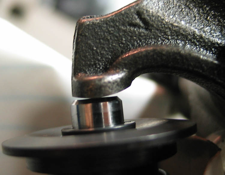
I did decide that the pushrod length is probably okay. I don't think you can't really check non-roller tip rockers by looking at the tip wear pattern, they pretty much wipe all across the tip. Instead I just looked for the contact point of the rocker at mid-cam lift to be centered. As you can see in the picture below it isn't too bad, maybe a little towards the inside.
September 12th, 2004
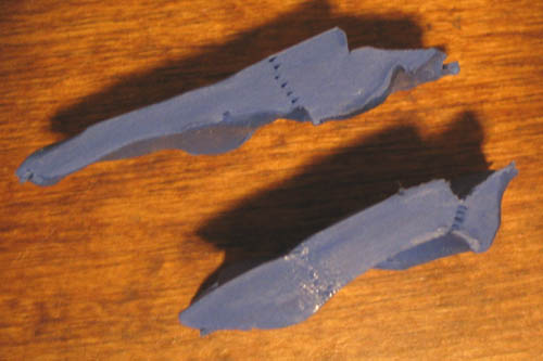
Friday after work I did the valve to piston clearance check and it passed easily. The minimum spec is .08" intake and .10" exhaust. I got .17" intake and .26" exhaust so I'm in good shape. I _could_ correct the cam to straight up, but I've decide not to. The 2 degrees advanced looks good in Desktop Dyno, giving a bit more torque and moving both peaks down 500 rpm at the cost of 3 hp on the top. Pictures of the clay and where I measured it is below. The closest approach on the intake was actually diagonally to the valve relief in the piston.
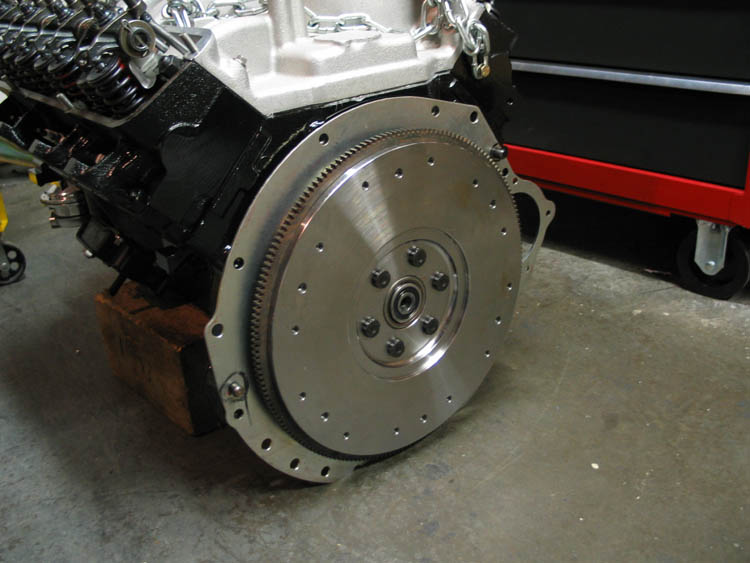
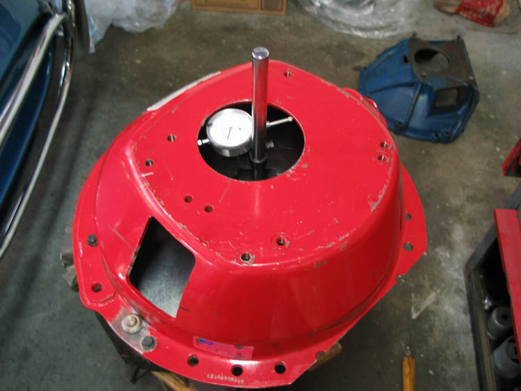
The final check list item before final build on the motor was to align the bell housing so that it is lined up with the crank centerline. I tipped the motor up on blocks with the flywheel end up. Then I put a dial indicator on the crank and spun it to see how far off it was. I was shocked to see that from the factory it was off .021" The spec is less than .010". I really don't understand why they can't make these more accurately than that, my crusty old cast iron bell housing was only off .004" and that didn't appear to be misalignment but rather the hole wasn't round. From what I've heard you almost always have to adjust them. There are two ways to adjust them, you can get offset dowels that you turn until it's lined up, but that seemed a little hokey to me, you have to be sure to line them up correctly. The other way is to drill the hole oversize and using longer dowels, weld a new collar to the bell housing in the right spot. I decided to do the weld on procedure. The problem with either method is you have to remove the original dowels that have been living in the block for 40 years in interference fit bliss. I could not budge them with vise grips. The real tool for the job is a slide hammer arrangement with a collet that clamps down on the pin, but I could not find one in a 1/2" size. I asked on several internet forums and one of the best suggestions was to use a sears bolt-out kit. I got one and was able to remove the first one fairly easily. On the second one I shelled out 3 of the bolt-outs and while I did move it, it was no where near out. I took the bolt out kit back to sears and they somewhat cheerfully exchanged them, it helped that I was asking about a tool chest that I had been eyeing. This time I got an even bigger set of bolt outs that were deeper and ended up having one with a really good bite on the dowel. So I could turn it but it still wouldn't come out. I tried heating the block but that seemed to make it tigher. I tried packing it with ice but that didn't seem to help either. Then the same guy who suggested the bolt out suggested using an impact wrench. That finally did the trick, I ran the impact and at the same time kind of leaned it over and pulled up slightly and after a long time it started to walk out. Next I drilled the two bell housing holes bigger, to 17/32". That turns out to not be enough, I'm at .012" now. I'll go get a 9/16" drill bit and finish it. The only question is whether my dinky little welder will do the job or not. I may have to call a portable welder guy.
UPDATE: I got up this morning (Monday) and decided to finish the bellhousing work. With the 9/16" holes I had plenty of movement available. The process of adjusting the bellhousing is a little like nailing jello to the wall, you have to loosen the fastners to move it, but each one you then tighten moves the bell housing a little. I ended up with everything tightened down and .007" on the dial. You divide that in half to compare to the .005" spec. I thought about trying for closer but at that point felt really lucky I had gotten where I did. So I welded the collars down, my welder worked fine. Then after it had cooled I took it completely off and put it back on and bolted it down in no particular order. Measured again and got .005", double the spec! So I'm happy, and glad to check that off my list. Now I think given the "end of the crank up" current presentation it would be a convenient time to put in the pilot bearing and bolt up the flywheel. Hopefully I can do that tonight and get the block back on the engine stand.
September 17th, 2004
Boy it's been a busy week. Work was crazy but I usually found time to make a little progress on the motor each day, usually in the middle of the night. I decided not to install the flywheel yet. I had to order a pilot bearing and I thought having the block plate installed would be a nuisance for painting the block. So I tipped the motor back over and put it on the engine stand.
Next I reinstalled all the pistons. I rechecked everything and used moly grease on the rod bearings instead of lubriplate. I had planned to use the nice rod bolt stretch gage I bought but ended up not using it. The main reason is that you really need to use the same method as the guy who reconditioned your rods so the big ends come out the same shape. I called Dennis at www.dscmotorsport.com and he said they use the torque wrench method. The ARP instructions say you should torque the bolts 3 times. So I figured he did it once already so I did it an additional 2 times.
Then I did the final install on the cam. I ended up pulling it out and touching up all the lubricants and putting it back. I also had to run out and get a #4 Phillips bit socket to torque down the thrust plate fasteners. Camshaft end play is right where it should be at .005". I also decided to install the cam as ground which is 2 degrees advanced. It did nice things to the curves in Desktop Dyno, giving more torque and moving the peaks down 500 RPM at the expense of like 2 HP.
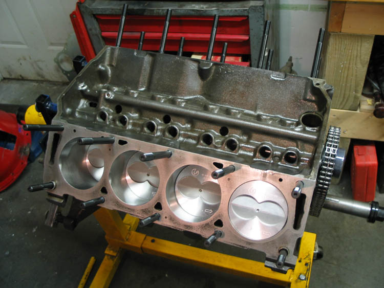
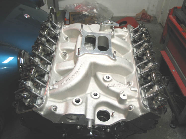
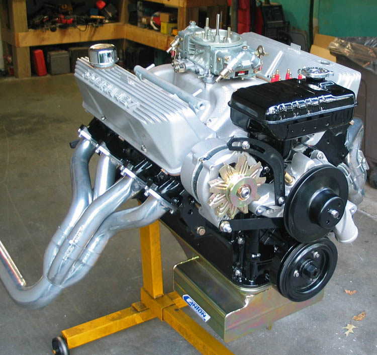
I then installed the heads because I really couldn't think of anything else to check. I used FelPro head gaskets and ARP studs. I like the idea of using studs wherever possible. It makes assembling things easier and doesn't wear the threads on the thing you are bolting to. Then I masked everything off and painted the engine gloss black. In 1965 Ford painted FE motors black with gold valve covers. In 1966 base motors started to be painted dark blue, but the 427 remained black. So Black is what most cobra guys do. I think the original would have been semi-gloss, but I thought gloss could be kept clean longer.
Next I decided to install the Canton road race oil pan and windage tray to see if there was any interference with the windage tray. I installed the stud kit that came with the pan and found a hole or two in the pan and windage tray that weren't in the right spot. So I filed a little bit and got it to fit. For the FE motor the windage tray bolts in the same way as the pan so you use 2 pan gaskets. But for this test I installed the windage tray with no gasket to see if the rod bolts would hit it. Unfortunately it did, not much but enough to get me worried. I called Canton and they said it might be okay with a gasket but if not send it back and they'd replace it. The tech was really surprised I had contact on a 3.78" stroke motor. Looking at it again I saw a little bit of a bend where the contact was so I "adjusted" it. With the gasket in place it cleared so I think it's fine.
Then last night I installed the lifters and did a check for push rod clearance in the holes through the intake. A couple of issues came out of this exercise, but the pushrod holes were fine. The deep grooved splash guards that go on the head didn't work with the Edelbrock intake. I had a set of new ones in the other style saved for the 427 that I used instead. I also noticed a problem with with the second rockershaft assembly, hmmm... only 7 rockers on it. So once again the 427 parts offered up a rocker to the 390. I'll have some replacing to do when I get around to building the 427.
At this point I see no barrier to finishing up the motor tomorrow.
September 18th, 2004
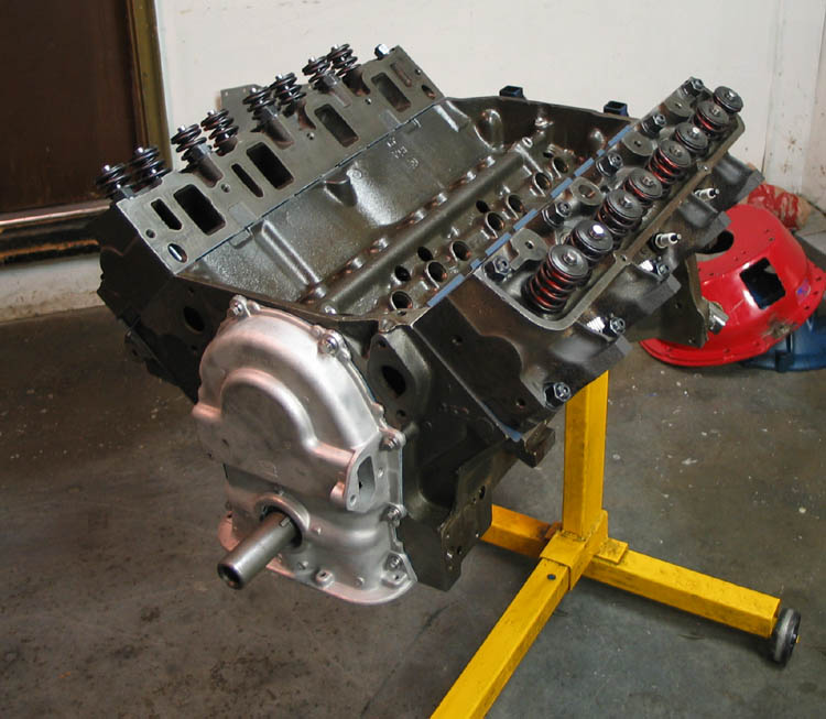
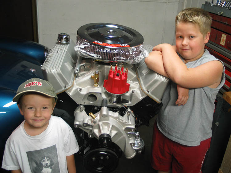
I think we can now officially say the motor is built! The rest of the assembly was pretty uneventful. I didn't install the oil pump, pickup, windage tray, and oil pan yet because Charlie said it was harder to put the motor in with the pan in the way. When the boys got up at 8:00 I was pretty much done. They thought it looked pretty good.
September 19th, 2004
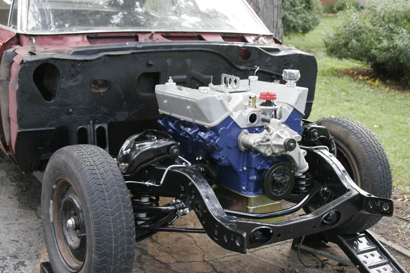
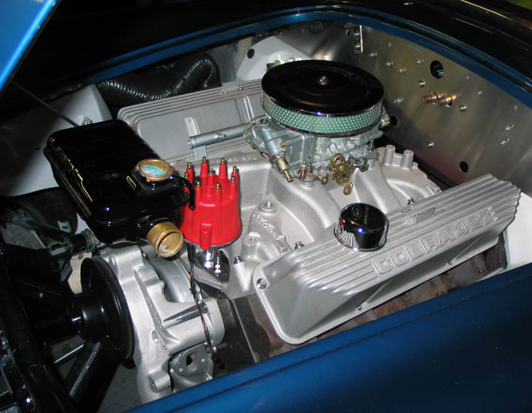
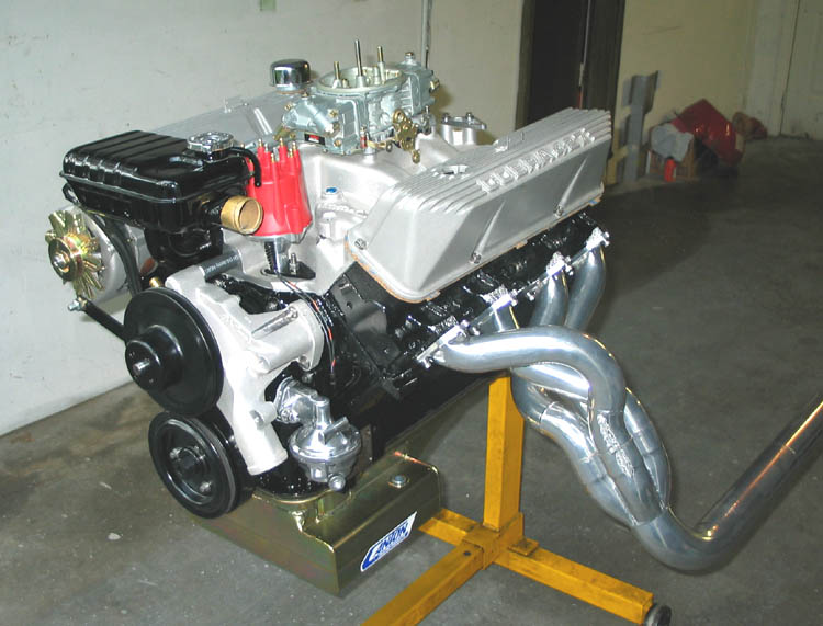
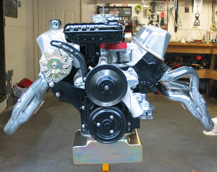
This morning I finished mocking up the rest of the motor including the headers and the alternator brackets. Everything worked good, and I think the airborn coatings ceramic on the headers looks great. I still need to make a fuel line from the pump to the log and make the plug wires, but really it's pretty much done.
September 25th, 2004
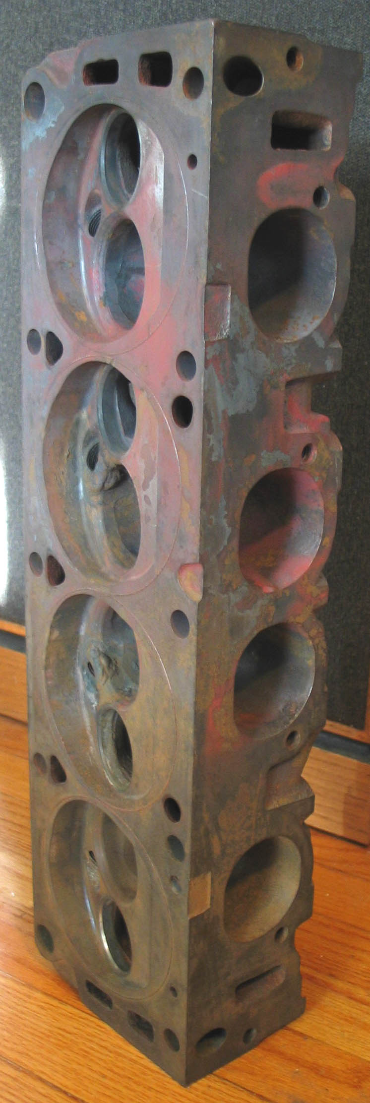
This posting isn't much about motor progress, although some has been made. It's more about a cool thing that happened on Friday. Let me first say that I am never in the right place at the right time, and many would argue that I still wasn't, but it did feel like I was. Our neighbor across the street had been helping a friend of his clean out his machine shop getting ready to retire. He had been telling me there was some ford parts that would eventually be for sale, and that he'd let me know. Well Friday I got the call and Duncan and I hurried down there late in the afternoon. This is an old Kansas City machine shop that was this guy's fathers before him. At one time they did all the work on Offenhauser engines in the country. Anyway, my friend directed me to the what was left of the ford stuff, about a dozen heads. The real "find" or not, was right out in front. A rare 427 Tunnel Port head. Only one and it had been welded in two cylinders. Also in the pile were two late FE heads, those that came standard on 390s in Fairlanes and Mustangs. They have a unique exhaust bolt pattern for the manifolds for these cramped engine compartments. Anyway, I talked to the guy, a really interesting fellow. I asked him if he'd sell me his tunnel port head. He said sure, and asked me what I'd offer for it. Geez... I hate it when they do that, but they seem to always do that to me... So I shot him a price based on "this is a thousand dollar head if it can be fixed, but it could just as likely be a very cool paperweight". He said that's about what I was thinking too, is there anything else you could use? I was going to say no, but said I was looking for FE stuff. He talked me into taking the other two heads too for the price I offered as they were rebuilt with new guides, one was assembled, the other was mostly bare.
What are tunnel port heads you might ask? They are a late over the counter racing head, probably developed for NASCAR. They have the largest valves ever fit in a 427, 2.25" intake and 1.75" exhaust. The feature that gives them their name is a huge oval intake port. The limiting factor for intake capacity became the space between the push rods through which intake port must pass. To get around, this the port goes through the pushrod, or I should say the push rod passes through a tube in the middle of the intake port on the intake manifold. They first made these heads in '67 and continued through about '70. They really need high RPM to really show their stuff. Some cobra guys use them, as well as at least one GT-40 that I saw at the Monterey Historics in 2003. Drag racers used them too, this particular head has o-rings installed to help seal the cylinders for supercharging.
So what do I have? I had heard that cracks in these heads are common and that is what they guy said I bought it from. He said that the best head welder in the country worked on this head and he was certain it could be used again. The repair had been done right and it was typical of these heads to need it once and then be good from then on. To use it I would need to stumble onto another head and an intake. It could happen... but until then it's a very cool thing to look at.
October 2nd, 2004
This morning I got the engine put back in the car. First I took it off the stand and set it on 6x6 blocks on the floor. I then installed the pilot bearing, backing plate and flywheel. Next I put the engine back in, following Charlie's recommendation to leave the oil pan off, and using the same over the fender approach shown above. I did something a little risky, I left it hanging on the mounts while I rolled the car back into the garage. It seemed pretty solid though and I don't think I should have hurt anything. As soon as I got it in a good spot I put a bottle jack under the back of the block to fully support it. If I had it to do over I would probably have cut a 2x4 to set on the frame rails to support the back of the engine, that would have been smarter. Also stumbled onto a trick that made doing all this by myself a lot easier. I was using 2 chains to the heads and an engine leveler (the carb lift plate is just on the engine to keep debris out of the intake). To use that I needed to twist the engine a little while lowering the hoist. So I thought needed a rope, but I couldn't find one, so I used some scrap tool box liner. The trick is that the tool box liner material was sticky enough that I could lay it on the fender and it would hold the twist. Next step is installing the clutch, bellhousing and transmission...